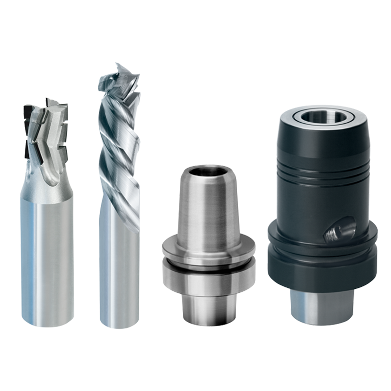
Tools for machining in the nesting process
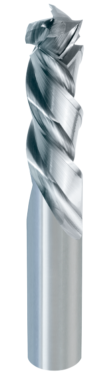
Finishing Cutters GIGASPEED solid TC
| D (mm) |
L2 (mm) |
L4 (mm) |
L1 (mm) |
Shank (mm) |
Part-No |
|---|---|---|---|---|---|
| 8 | 20 | 6 | 80 | 8 | 20250-6-08020-R |
| 10 | 25 | 6 | 90 | 10 | 20250-6-10025-R |
| 10 | 30 | 6 | 90 | 10 | 20250-6-10030-R |
| 12 | 30 | 6 | 100 | 12 | 20250-6-12030-R |
| 12 | 35 | 6 | 100 | 12 | 20250-6-12035-R |
| 12 | 40 | 6 | 100 | 12 | 20250-6-12040-R |
| 14 | 35 | 8 | 100 | 14 | 20250-6-14035-R |
| 16 | 35 | 8 | 110 | 16 | 20250-6-16035-R |
| 16 | 40 | 8 | 110 | 16 | 20250-6-16040-R |
| 16 | 45 | 8 | 110 | 16 | 20250-6-16045-R |
| 18 | 45 | 8 | 108 | 18 | 20250-6-18045-R |
| 20 | 45 | 10 | 130 | 20 | 20250-6-20045-R |
| 20 | 50 | 10 | 130 | 20 | 20250-6-20050-R |
| 20 | 55 | 10 | 130 | 20 | 20250-6-20055-R |
20250-6
Technical design
Three staggered solid TC spiral cutting edges each, with maximum alternative shear cut. Parallel shank.
Cutting on bottom and periphery. Right-hand rotation. For mechanical feed.
Application
For grooving, jointing, finishing, sizing of long fibrous or very soft worpiece materials (e.g. poplar plywood) and coatings / laminations (veneer, decor papers), soft and hard solid wood, as well as for MDF and Mulitplex. Also recommendable for nesting operations of plasterboard.
Limited recommendable for chipboard.
*****
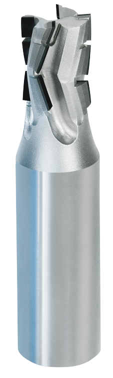
Diamatic-QUATTRO
| D (mm) |
L2 (mm) |
L4 (mm) |
L1 (mm) |
Shank (mm) |
Part-No. |
|---|---|---|---|---|---|
| 16 | 21 | 12,7 | 85 | 20 x 55 | 15556-9-16215-R |
15556
Technical details
- tool body made of high-density metal
- periphery tips and plunge tip made of pcd
- alternative shear cut
- several times resharpenable
Application
- grooving, sizing and severing of chip- and MDF-boards
- applicable for axial- and ramp plunge cutting
Special advantages
- especially applicable for nesting operation
- optimal for board thicknesses of 16 mm and 19 mm
Application data
n = 18 000 - 24 000 min-1
vf = 20 - 40 m/min
Criteria for optimal nesting results:
-
With the feed rates mentioned, work is carried out in the optimum tooth feed range, thus achieving a high machining speed and high-quality finishing on the narrow sides of the workpieces.
-
The long clamping length and rigidity of the shank minimizes unwanted vibrations and reduces the bending moment between the tool and the clamping device.
-
The cutting length of the tool should ideally be only slightly greater than the thickness of the workpiece so that the machining forces are as close as possible to the clamping, further minimizing the bending moment. For large material thicknesses, it is also advisable to increase the shank diameter.
-
The base body material of the tools is of decisive importance for the machining quality and tool life. Base bodies made of heavy metal or solid carbide are vibration-damping and insensitive to fracture and dissipate the heat generated at the machining point well in the direction of the shank.
-
In nesting, optimized chip disposal is particularly important compared to other machining operations. In slot milling, there is anyway a tendency for a large proportion of the chips to remain in the bottom of the slot; this tendency is reinforced by the suction effect of the vacuum during nesting. The JSO nesting cutters feature an optimized chip space design and - especially in combination with the PREZISO suction turbine - enable almost complete removal of the chips from the groove.
- The optimized cutting geometry ensures low machining forces, which is particularly advantageous for small workpieces that can be easily displaced on the sacrificial plate due to the small contact surface and the resulting reduced holding forces of the vacuum.
-
The diamond or carbide grades used are optimally matched to the materials to be machined and achieve far above-average tool life.
Which clamping devices are suitable for nesting machining?
We recommend the use of heat shrink chucks or hydro chucks that have a correspondingly good concentricity in order to take full advantage of the tool path optimized tools:
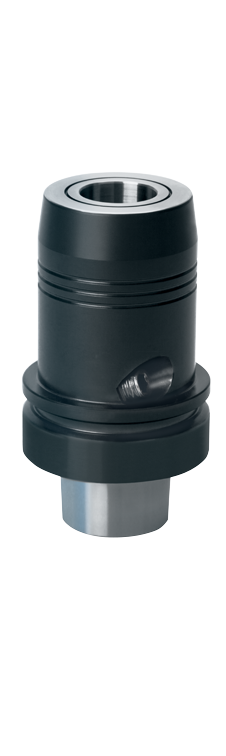
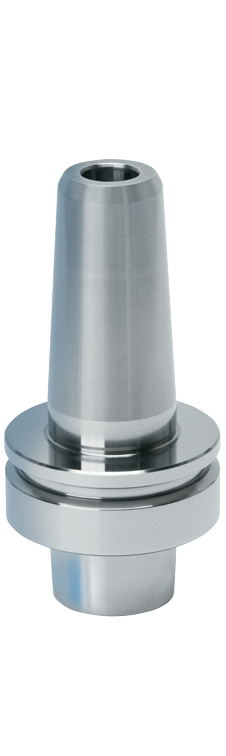
Hydraulic Clamping Chucks
| d (mm) |
D (mm) |
A (mm) |
L5 (mm) |
L3 (mm) |
L1 (mm) |
Part-No. |
|---|---|---|---|---|---|---|
| 10 | 30 | 80 | 31 | 34 | 105 | 21016-0-10063-0 |
| 12 | 32 | 80 | 36 | 34 | 105 | 21016-0-12063-0 |
| 16 | 38 | 80 | 39 | 34 | 105 | 21016-0-16063-0 |
| 20 | 52,5 | 80 | 41 | 54 | 105 | 21016-0-20063-0 |
| 25 | 52,5 | 90 | 47 | 64 | 115 | 21016-0-25063-0 |
21016
Technical details
Tempered and ground tool body. Thoroughly balanced for R.P.M. max. 25 000.
Application
For high-precision clamping of parallel shanks.
For either right-hand or left-hand rotation.
Main Advantages
- Highest concentricity (< 0,003 mm)
- Optimum balancing quality
- Higher clamping precision
- Higher clamping power
- Vibration-damping
*****
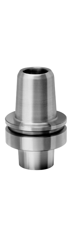
THERMOTEC Heat Shrinking Chucks
| d (mm) |
D2 (mm) |
D (mm) |
L2/L3 (mm) |
L1 (mm) |
Part-No. |
|---|---|---|---|---|---|
| HSK- F63 |
|||||
| 6 | 23 | 27 | 23/49 | 100 | 21022-0-06063-F |
| 8 | 23 | 27 | 38/49 | 100 | 21022-0-08063-F |
| 10 | 28 | 32 | 40/49 | 100 | 21022-0-10063-F |
| 12 | 27 | 33 | 45/49 | 100 | 21022-0-12063-F |
| 14 | 29 | 34 | 46/49 | 100 | 21022-0-14063-F |
| 16 | 30 | 36 | 50/49 | 100 | 21022-0-16063-F |
| 20 | 34 | 39 | 55/49 | 100 | 21022-0-20063-F |
| 25 | 37 | 43 | 55/49 | 100 | 21022-0-25063-F |
| 30 | 44 | 51 | 57/50 | 100 | 21022-0-30063-F |
| HSK-E 63 | |||||
| 16 | 30 | 36 | 50/49 | 107 | 21022-0-16063-E |
| 20 | 34 | 39 | 55/49 | 107 | 21022-0-20063-E |
| 25 | 37 | 43 | 55/49 | 107 | 21022-0-25063-E |
21022
Technical details
High precision tool holder with thermical tool clamping for shank tolerances according to Standard EN 847-2.
Precision balanced for maximum R.P.M. = 30 000.
Short, slim design - as Thermotec Plus / Extreme in slim, extended design: on demand.
3,3° conicity of the thermo cone.
Application
For high precision clamping of solid TC and steel shanks.
Especially suitable for HSC machining. Improved milling results thanks to precise run-out.
Suitable both for either right-hand or left-hand rotation.
Special advantages:
- Highest concentricity and repeat accuracy (< 0,003 mm)
- Optimum balancing quality
- Suitable for HSC-machining
21022 PLUS
| d (mm) |
D2 (mm) |
D (mm) |
L2/L3 (mm) |
L1 (mm) |
Part-No. |
|---|---|---|---|---|---|
| HSK- F63 |
|||||
| 6 | 19 | 25 | 35/64 | 115 | 21022-0-06163-F |
| 8 | 19 | 25 | 38/67 | 118 | 21022-0-08163-F |
| 10 | 24 | 31 | 40/70 | 121 | 21022-0-10163-F |
| 12 | 27 | 34 | 45/74 | 125 | 21022-0-12163-F |
| 14 | 29 | 36 | 46/76 | 127 | 21022-0-14163-F |
| 16 | 30 | 38 | 50/79 | 130 | 21022-0-16163-F |
| 18 | 32 | 40 | 50/79 | 130 | 21022-0-18163-F |
| 20 | 34 | 41 | 55/82 | 133 | 21022-0-20163-F |
| 25 | 37 | 45 | 55/82 | 133 | 21022-0-25163-F |
| 30 | 44 | 51 | 61/82 | 133 | 21022-0-30163-F |
| HSK-E 63 | |||||
| 16 | 30 | 38 | 50/79 | 137 | 21022-0-16163-E |
| 20 | 34 | 41 | 55/82 | 140 | 21022-0-20163-E |
| 25 | 37 | 45 | 55/82 | 140 | 21022-0-25163-E |
*****